
Flagship opportunity · In diligence
Sri Lanka.
A phased compute deployment on the north-west coast, built around the power on site.
Compute platformNVIDIA Vera Rubin NVL72 (VR200)
Explore Sri Lanka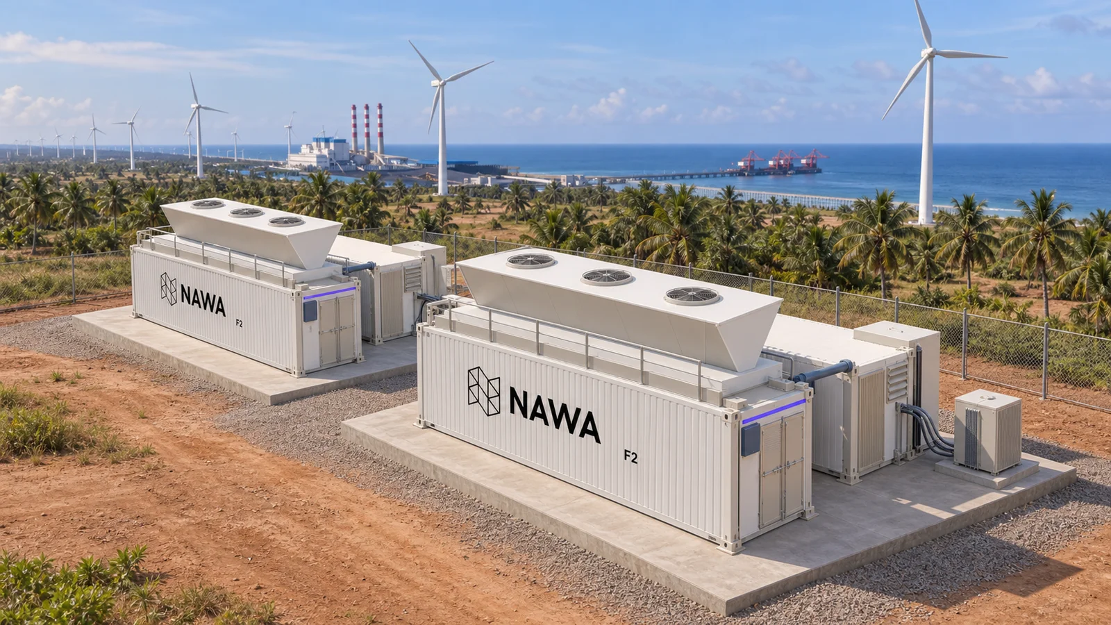
Power exists in extraordinary places.
We bring the infrastructure to use it.
The Nawa model 01 / 03
We bring compute to available power: wind, solar, biogas and flare gas. Each site starts with nameplate capacity and a clear view of what it can reliably deliver.
We bring compute to available wind, solar, biogas and flare gas, starting with reliable power behind the meter.
Fuel cells and gas generation unlock opportunities close to the source. Fuel quality, continuity and site conditions guide the design.
Find the power. Build around the site.
Accelerator racks, liquid cooling, roof-mounted heat rejection and UPS come together in a repeatable container system.
Liquid-cooled accelerator racks, roof-mounted heat rejection and protected power, in one repeatable system.
Dual cooling distribution units serve the racks. Trim chillers support the network and air systems, with batteries housed separately.
Designed around NVIDIA reference specifications.
For offtakers and neoclouds, we match compute to real workloads. Our potential sites bring available power closer to demand.
We match compute to real workloads, connecting potential sites with offtakers and neoclouds.
Sri Lanka leads our pipeline. Potential sites across the US and selected international markets are in diligence or under review.
Potential deployments · Site and commercial review
Power exists in extraordinary places. We bring the infrastructure to use it.

The Nawa model

We bring compute to available wind, solar, natural gas and biogas. Dependable power, fuel supply and site conditions shape each deployment.
Behind-the-meter power
We work with wind providers to place compute close to renewable generation. Hourly output, curtailment and firming requirements shape the capacity a site can support.
Generation matched to demand
Co-located solar can supply daytime demand behind the meter. We size around the generation profile and assess storage or complementary generation for continuity.
Natural gas · Conditioned biogas
Fuel cells convert natural gas or conditioned biogas into electricity electrochemically. Co-location with biogas facilities starts with gas cleanup, fuel continuity and a suitable generation system.
Available generation · Fuel diligence
We assess existing nameplate generation and opportunities around biogas and flare gas. Gas composition, pressure, treatment and dependable net output determine the site design.
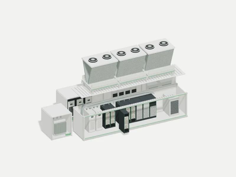
NAWA F2 brings liquid-cooled accelerator racks, roof-mounted heat rejection and protected power into a repeatable container system.
NAWA F2 cooling system
Two internal CDUs serve a 45°C rack supply loop and keep it separate from facility water. Roof-mounted heat rejection handles the main liquid loop; trim chillers support networking and residual air loads.
Power conversion · Battery ride-through
A dedicated electrical module distributes protected power, supported by UPS equipment and separate battery modules. Ride-through capacity is sized to the site and its supply transitions.
Rack-scale compute
Liquid-cooled accelerator racks bring compute, high-speed fabric and power delivery into a repeatable module. Rack integration follows the platform reference design.

We match compute to real workloads, connecting potential sites with offtakers and neoclouds. Sri Lanka leads our pipeline, with selected markets in diligence or under review.
Potential deployments
NAWA F2
Compute, cooling and power. Built to work together.
Vera Rubin NVL72 racks sit inside the IT module. We coordinate the rack layout and integration with our silicon partners.
Liquid cooling carries heat from the chips to the roof equipment. Separate cooling supports the room and network hardware.
The power module brings distribution, UPS protection and batteries together. Its connection to grid and backup sources is engineered for each site.
Network cabinets connect the compute inside each cell. Fiber links join the cells and carry traffic to the site’s carrier handoff.
Foundations, power connections, fiber access and service clearances complete the deployment. Each site’s infrastructure sets the starting point.
The cell

Plan and elevation. F2 layout, September 2026. Not to dimension.
Hover to explore. Select a component to pull it out.
The deployable unit is a two-container cell in standard ISO boxes: an IT box carrying six NVL72-class racks with their fabric, and a power box carrying the switchboard and the UPS. The pair is tested together at the factory and re-joined on site with one busduct connection. It stacks from one cell to a campus, and the module set stays the same across geographies and voltage standards.
Share the capacity, location and timing you need. We’ll assess how it fits a Nawa deployment.
We work closely with silicon partners to ship racks in as little as four months, coordinating hardware supply with the infrastructure that will power and cool it. Timing depends on configuration and availability.
Plan your deploymentDeployments
Sri Lanka leads our development pipeline. Across selected markets, we are assessing sites and working through the power, connectivity and commercial foundations for compute.
Flagship opportunity · In diligence
A phased compute deployment on the north-west coast, built around the power on site.
Compute platformNVIDIA Vera Rubin NVL72 (VR200)
Explore Sri Lanka 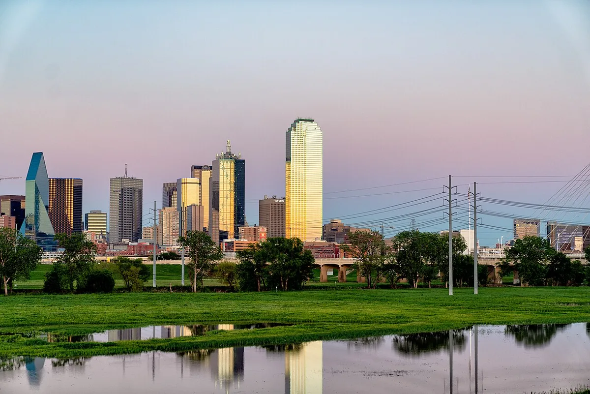
An existing facility opportunity in North Texas is under assessment.
Explore opportunityRegional photography · Tony Webster
CC BY 2.0 · Resized.
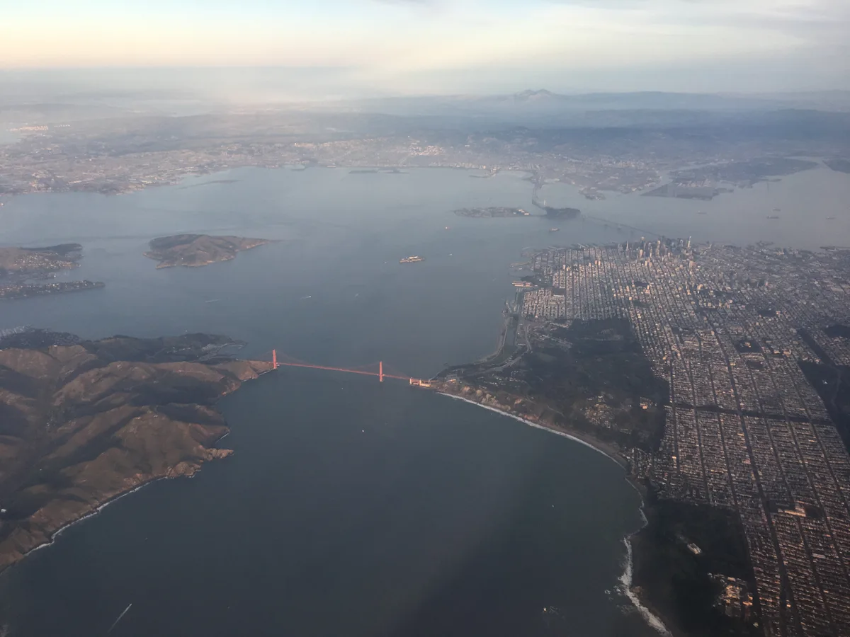
We are assessing a Bay Area opportunity for compute close to demand.
Explore opportunity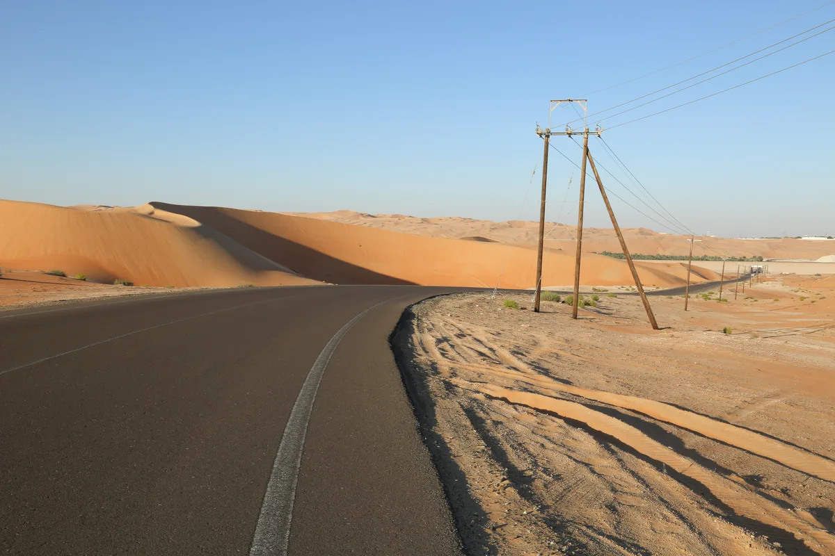
We are evaluating a phased compute project in the United Arab Emirates.
Explore opportunityRegional photography · JSPhotography2016
CC BY-SA 4.0 · Resized.
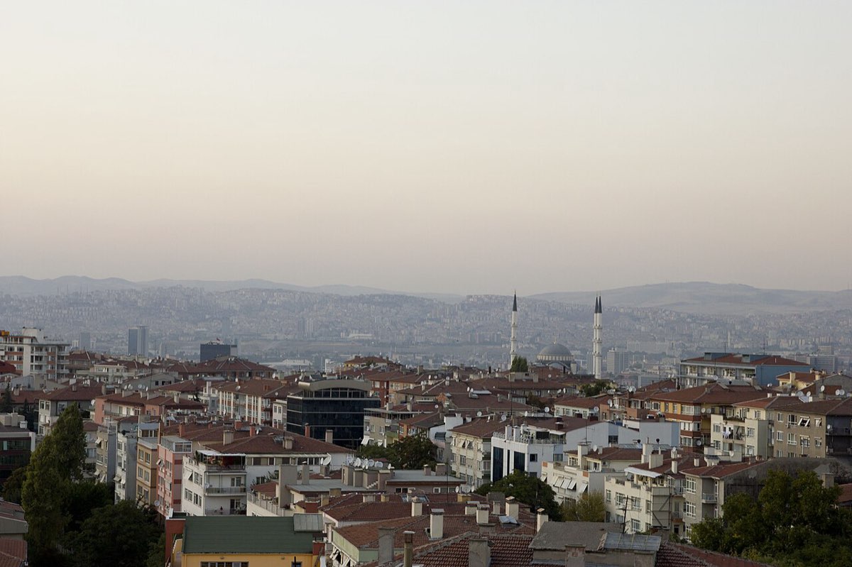
Türkiye remains a market under assessment for modular compute.
Explore opportunityRegional photography · William Neuheisel
CC BY 2.0 · Resized.
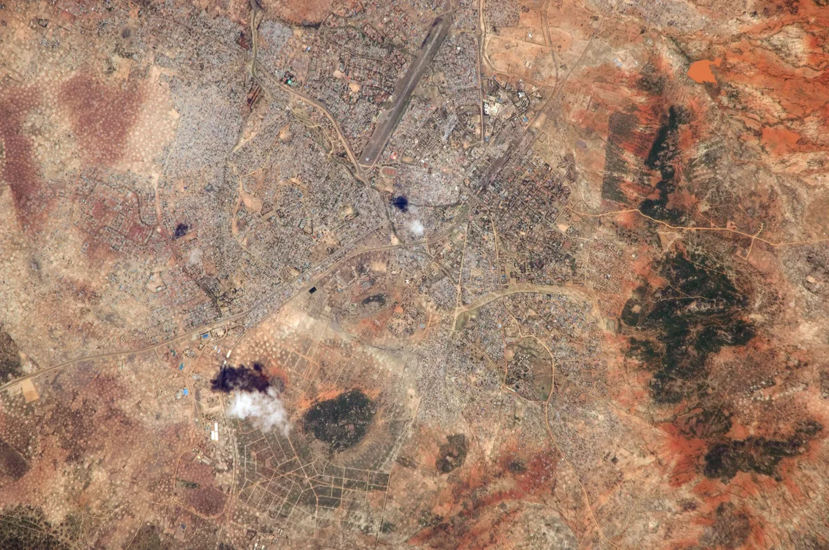
Tanzania is under assessment for compute near regional power infrastructure.
Explore opportunityRegional photography · NASA
Public domain · Resized.
Development pipeline
3 in diligence · 3 under review
Another route to power
We develop opportunities to colocate modular compute with biogas facilities and sites with reliable natural gas. On-site fuel cells convert conditioned gas into electricity for the racks, bringing generation and compute together at the same site.
We assess fuel quality and volume, site access and fiber together, then size the power plant and compute deployment around what the location can support.
Bring us a gas or biogas siteCompute
Nawa develops and commercialises modular GPU infrastructure for inference workloads and flexible hourly consumption.
Dedicated and reserved capacity for production inference workloads, deployed through infrastructure Nawa develops and operates close to where the output is consumed.
Hourly access to GPU capacity for teams that need accelerator time without owning the hardware, served from deployments Nawa develops and operates.
Need dedicated capacity or a custom deployment? Speak with our infrastructure team.
Request computeThe unit behind each deployment is drawn at /models, with every figure sourced.
Who we work with
Nawa is designed for workloads where location, latency, control, or resilience shapes the infrastructure.

Edge infrastructure for organisations that need compute and data to remain within a required jurisdiction.

Compute placed near users and devices when interaction depends on a tight response budget.

Infrastructure for vision-language and vision-language-action systems that connect models to the physical world.

Controlled, resilient infrastructure for public-sector and defense applications with specific location and operating requirements.
Request compute, expand your cloud, or submit a site for development. Share your requirements, then book a call with our team.
Offtakers
For AI teams, enterprises and offtakers seeking GPU capacity. Share your workload and delivery requirements so we can assess a suitable deployment. Brokers representing a buyer are welcome.
Neoclouds
For neoclouds expanding their GPU footprint. Work with Nawa on powered sites, modular infrastructure and rack deployment, with an operating structure built around your platform.
Landowners
For landowners, developers and authorized site representatives. Submit land or an existing facility for a potential Nawa deployment, with the power position and terms you can offer.


.jpg)

